Published On Jan 6, 2015
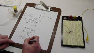
NPN and PNP transistors are two complementary types of bipolar junction transistors (BJTs). They both work the same way: when current flows thru the Base-Emmitter junction, the transistor "turns on", and creates a current path through the Collector-Emmitter junction. The amount of current that will flow through the C-E junction (our "Load" current), is determined by the amount of current flowing thru the B-E junction (our "Control" current). (The C-E current is typically larger than the B-E current, and it's equal to the B-E current multiplied by some value, called "hFE" or "common emitter current gain".)
The only significant difference between an NPN and a PNP transistor is that to turn on an NPN transistor, current flows IN to the Base and OUT of the Emitter; we accomplish this by applying a positive voltage to the Base relative to the Emitter. To turn on a PNP transistor, current must flow IN to the Emitter and OUT of the Base (the opposite direction of NPN), and to accomplish this we a apply a negative voltage to the Base RELATIVE TO the Emitter. That is why you see things like "-5V" in a datasheet for PNP. Usually the Emitter is "common" and thus a voltage reference for the Base.
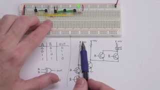
Bipolar transistors are often used as simple switches in a "common emitter" configuration. For NPN transistors, we tie the Emitter to ground and turn the transistor on by applying a voltage to the base that is higher than ground; the Collector provides a "switched ground" output (either "open" or tied to ground).
For PNP transistors, we tie the Emitter to our positive power supply rail, and turn the transistor on by applying a voltage to the base that is lower than the positive power supply rail; the Collector provides a "switched positive" output (either open or tied to the positive power supply rail).