Published On Oct 14, 2019
▶ C'mon over to https://realpars.com where you can learn PLC programming faster and easier than you ever thought possible!
=============================
▶ Check out the full blog post over at
https://realpars.com/spool-valve-sche...
=============================
⌚Timestamps:
00:00 - Intro
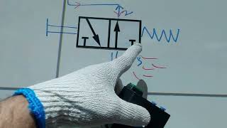
01:03 - Pneumatic Valve Symbol
02:15 - Two-Position Spool Valve Symbol
03:20 - Three-Position Spool Valve Schematic
=============================
In this video, we will learn about how a spool valve is represented in engineering and manufacturers' drawings, how to understand what the drawing means and how it relates to the operation of a valve.
As we already know directional air valves, in particular, spool valves, are the building blocks of pneumatic control.
In engineering drawings, pneumatic circuit symbols provide detailed information about the valve they represent.
Symbols show the methods of actuation, the number of positions, the flow paths and the number of ports a valve has.
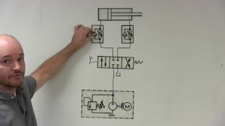
When we see a valve schematic, we can see it is made up of boxes, each containing a number of lines and arrows.
The number of boxes that make up a valve symbol indicates the number of possible positions the valve has.
Flow direction is indicated by the arrows in each box. These arrows represent the flow path the valve provides when it is in each position.
To the left and right of the boxes, we can see the types of actuators being used;
In some cases, there will be a single actuator at one end of the boxes and a spring return at the other end. In other cases, there may be an actuator at both ends.
The 3-position valve has both solenoids and spring return actuators on both sides of the valve, the spring return actuators will return the valve to the middle position but only IF neither of the solenoids is active.
In this example, the middlebox indicates that there will be no airflow at all until one of the two actuators is active.
It should be noted that colors are used in this video only to assist with learning.
In practice, the schematics you see on a day to day basis will not have any colors.
A typical use for the type of valve would be to bump or inch a cylinder incrementally along its stroke length by pulsing one of the actuators.
The number of ports a valve has is shown by the number of endpoints in a given box.
We should only count the ports in a single box once per symbol.
For example, in the 3-position valve, there are three boxes that show the three possible positions, but the valve has five physical ports.
So the valve will be called a 5/3 solenoid valve.
You may also see some manufacturers use letters instead of numbers to identify the ports, but once you understand the schematic it is easy to translate this.
=============================
Missed our most recent videos? Watch them here:
https://realpars.com/dcs-vs-scada/
https://realpars.com/simatic-tdc/
https://realpars.com/starter-commissi...
=============================
To stay up to date with our last videos and more lessons, make sure to subscribe to this YouTube channel:
http://goo.gl/Y6DRiN
=============================
TWEET THIS VIDEO https://ctt.ac/dodpN
=============================
Like us on Facebook: / therealpars
Follow us on Twitter: / realpars
Follow us on LinkedIn / realpars
Follow us on Instagram / realparsdotcom
#RealPars #Automation #SpoolValveSchematic