Published On Apr 13, 2020
• Our Facebook page: / diy.experiments.youtube
• How it works?
The electronic circuit transforms efficiently the direct current from the power supply into a sine current having a high frequency of near 100 kHz.
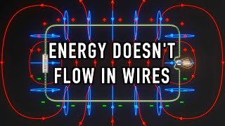
We need the current in the emitter to vary constantly in order to get a varying magnetic flux. Then, a varying magnetic flux can generate electricity remotely in the receiver coil. This is induction.
To better visualize this invisible energy vector, it’s possible to make an analogy with light which is an electromagnetic wave. It's possible to convert electricity into light, then the light can be converted back into electricity with a solar cell. The overall efficiency is lower, but it works.
The fact to use induction to transfer power is not new, transformers works the same way, there are using a solid core to lead the magnetic flux from the primary to the secondary coil. It’s essential to lead the magnetic flux because if a fraction of the flux doesn’t reach the secondary coil, the coils coupling is reduced and so is the efficiency.
With wireless power transmission, the aim is precisely that nothing is between the two parts. Consequently, it’s impossible to retrieve entirely the magnetic flux, especially when the distance is higher than the coils size. We are forced to send out more power that the useful load power.
Luckily, there is a way to partially overcome this problem. We use resonance. The resonance here means the fact that a coil and a capacitor can exchange energy each other.
In short, if a capacitor discharges in a coil, the coil produces a magnetic field. Once the capacitor is fully discharged, the magnetic field vanishes, so it varies and the coil produces back a reverse voltage in the capacitor, and so on.
This resonance can only occur at a precise frequency which depends on the coil inductance L and capacitor capacity C. It’s called an LC circuit.
So, great, the inductance and the capacitor can exchange energy, but why does it allows us to retrieve more energy?
The receiving coil produces a voltage according to the varying magnetic flux, but the coil has a drawback, as any coil, is has an inductance which narrows the current.
The inductance of the coil doesn’t reduce the current by loosing energy like a resistor, it rather delays the current variation by storing and releasing energy. The higher the frequency, the more the current is impeded. That’s why the generic link between voltage and current is called the impedance.
The fact is, when in an LC circuit is tuned to its resonance frequency, the coil and the capacitor impedances cancel each other. This way, we are completely removing the coil limitation and the resonance allows us to retrieve more energy. The resonance also increases the output voltage so it’s easier to supply loads.
Finally, the resonance forces the receiving coil to retrieve a higher fraction of the magnetic flux. The coupling between the emitting and receiving coils is increased, so is the flux density between the two coils.
The difference with or without the resonance isn’t negligible, for instance, the lamp’s filament turns from barely red to almost its melting point.
To get the resonance, as you understood, we simply need to add a capacitor in parallel with the coil. But there is one condition to follow, the resonance frequency should be as close as possible to the emitter frequency, in our case near 100 kHz.
We have to adjust precisely the capacity with one or several capacitors according to the coil inductance and the frequency. The simple fact to space out the two spins of the coil changes enough it’s inductance to detune the circuit.
About the emitter electronics, it’s a zero-volt switching circuit able to maintain a resonance between the emitter coil and its capacitor. It’s an efficient way to get a high frequency sine current in the emitter coil.
About the overall efficiency, it’s rather weak, but in short distances with identical coils we reached more than 80%.
The main issue it that the retrieved power decreases quickly depending on the transmission distance.
As a workaround, we use a different geometry in our magic carpet, the emitting and receiving coils are in the same plane. When we move away from one edge, we get closer to another.
This way, the power decreases slowly with the transmission distance and it’s easier to maintain a constant power requirement on several axes.
The magic carpet requires 2A with 24V when there are no supplied devices.
The current can reach 3A when all devices are inside. Only this over-consumption corresponds to the energy consumed by the devices. Thus, the overall efficiency is better when there are many devices.
Thanks for reading, ask us any question :)