Published On Jul 8, 2015
Arduino Tutorial: LED Sequential Control- Beginner Project
Inexpensive Arduino Starter Kit: http://amzn.to/1CqGEuB
Link to Arduino IDE: https://www.arduino.cc/en/Main/Software
Link to Sketch for this project: https://www.dropbox.com/s/bivwdnehp7l...
Today I am going to show you guys a very simple arduino project for beginners. We’re going to get three different LEDs to turn on and turn off in a simple sequence, like you see here.
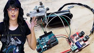
For this, you’re going to need an Arduino Uno or similar Arduino board, a breadboard (preferably with a positive and negative rail like this one), four breadboard jumper wires, a USB cable to for the Uno, three LEDs of different colors(here we are using Blue, Red and Green) and 3 220ohm resistors. Now we’re using 220ohm resistors, because they seem to work best with the LEDs we have- but you could use different resistors, depending on your LEDs and your circuit. I’ve put a link to an inexpensive arduino kit that contains all these components in the description below, in case you’re looking to get an arduino uno and all the basic components for this tutorial.
So lets first setup the hardware. The first step is to establish a common ground. To do this, use a jumper wire to connect the Ground pin on the arduino to the negative rail on the breadboard. This allows all the LEDs to use the ground pin on the arduino. Now we’ll insert the resistors into the breadboard. Space the resistors out with one leg connected to the the negative rail. Now its time to insert the LEDs. Before inserting the LEDs, its important to note that the longer of the two leads on most through-hole LEDs is the positive leads. Connecting it the wrong way, will cause this circuit to not work. Connect the negative lead of the LED to the horizontal rail on which the resistor is connected and connect the positive lead to an adjacent rail. Repeat this process for all three LEDs. Now its time to complete the circuit. We are going to use output ports 13, 12 and 11 for the input signal. Connect the positive lead of the LED on the right to pin 13, the LED in the center to 12 and the LED on the left to pin 11. The circuit is now complete. Power on the Arduino Uno by connecting it to your computer using the USB cable. The LEDs on the board turn on and the board powers up.
Before we work on our sketch, make sure to download the Arduino IDE for your specific operating system. I’ll leave a link to where you can download this software, in the description below. Once you’ve downloaded and installed the arduino IDE, go ahead and download the Sketch to run this program, using the link I’ve put in the description.
https://www.dropbox.com/s/bivwdnehp7l...
Open the downloaded file. The program first creates 3 variables. LED1, LED2 and LED3. This allows us to change the output pins, without having to modify the entire program. The code in the setup part of the program tells the arduino that pins 13, 12 and 11 will be outputs. The loop portion of the program is where the actual instructions live. The first three digitalwrite functions turn on one LED at a time with a 200ms delay between each of them turning on. The next three digitalwrite functions turn off the leds with a 300ms delay between each LED. Now you can change the delay between each LED to change the rhythm of the LEDs turning on and off. I’ve found that using 200ms and 300ms gives it a nice smooth rhythm. Now you’re ready to upload the program to the board. Now click on the Tools tab of the Arduino Window, make sure the Arduino Uno is selected as your board and make sure you select the COM port your board is connected to. Most of the times there will be one COM port available and that will be the one you need to select. Click on the upload button on the top left hand corner of the screen to upload the program to the Uno. A green progress bar on the lower right hand corner will indicate upload progress. And unless any errors appear in the black message bar at the bottom of the screen, your board should now be running the program and the LEDs should be turning on and off like you can see here.
Hope this tutorial was useful. Please hit LIKE for more Arduino tutorials and subscribe to stay tuned.