Published On Mar 5, 2023
#belt #grinder #DIY
Guys, hello to everyone! I want to present you my new work, namely a large belt grinder. It all started with a project in a 3D modeling program. This is the project I have for this dnvais. And now I will tell you and show you step by step how I made it. It all started with the motor, it is a three-phase electric motor at 1350 revolutions per minute, the power here is probably 1-2 kilowatts, it is impossible to read it on the label. Then I made a 3D model of it on the computer and started designing the device. The parameters of the belt grinder provide for its operation with tapes from one to two meters long. Decided on the approximate diameter of the drive pulley, it's something like 160-170 mm. And he started working in the workshop precisely with the drive pulley. I decided to work according to the scheme I tested - a cut sheet of plywood and a metal sleeve. Everything is glued with glue and twisted with strong screws. The work is not difficult for me, since it is not the first time I do this. My lathes help me a lot in this. The next step was the production of rollers. I made two straight rollers with a width of 55 mm and a diameter of 60 mm from kaprolon, since I had it. 202 used bearings. And I decided to order a steel barrel roller, I didn't want to make it myself. But I regretted it, the video that the so-called master made for me had a stroke of 0.5 mm. And I resharpened it myself. In this video, I used bearings number 203. I turned the axle for it myself.
I decided to fasten the rollers to the axles with the help of corkscrew rings.
The next step was to cut out all the metal parts of the belt grinder from 10 mm thick sheet metal. I entrusted this work to the laser. He cut everything clearly, but some parts were twisted and had to be finished with a file.
Everything as usual, another failure.
First, I welded the base of the structure with tacks.
Then I hooked the motor to the transition plate.
And already welded it to the main sheet.
The motor is attached both with paws and through a flange.
The next thing I did was the barrel roller tilt mechanism.
The design is quite clear, and makes it possible to adjust the roller in different planes.
I printed the handles on a 3D printer.
The next stage, this is the main crossbar, I decided to make it from a pipe with a square section of 50*50*5 mm, and its niche will be the same square pipe, but with a size of 60*60*5 mm.
So far, I do not have a milling machine to make high-precision milled parts. I do what is.
The bolt holder is welded to the supporting main plate.
From a distance, it may seem that everything is almost ready, but there is still a lot of work ahead.
I am putting together the parts that are already there.
I cut out a couple of corners for the stop plate.
I cut the main table from a piece of stainless steel.
Next, you need to make the bars for the table, the task is not easy, but I can roughly imagine how to do it without a milling machine.
To press the lever with a barrel-shaped roller, I will use a furniture stop, I bought three, with different pressing force.
In the process of work, I will see which one is better.
I am installing a stop plate and a table.
I will paint everything nicely, this is also important.
I put the whole structure together.
Here he is, what a beauty, I like it very much.
Now will be the first run, I hope everything will work great.
With this diameter of the pulley and revolutions of the motor, the speed of the stitch should be 18 m/sec.
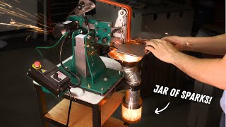
Great, I'm very happy, my build works, it's amazing.
Let's try it at work.
We hope for your likes and comments on the video. Share this video, I will be very grateful to you.
All the best, see you soon!