Published On Jan 20, 2021
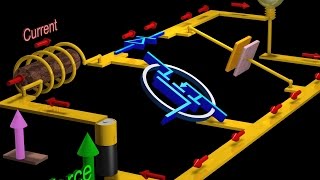
In this video we will explore the design and working of a closed-loop buck converter.
From its basic circuit to feedback driven circuit, we will explore it completely.
Correction: 6:05 - The duty cycle of PWM "increases".😅
Chapters:
00:00 - Introduction
00:17 - PWM
01:12 - Adding Inductor
02:30 - Frequency Increase
02:45 - Adding Capacitor
03:52 - Basic Buck Converter
04:13 - Closed Loop Buck Converter Circuit
04:20 - Operational Amplifier or Op-Amp
04:54 - Differential Op-Amp
05:30 - PWM Generator
06:08 - MOSFET
07:00 - Supply and Reference Voltages
07:25 - Normal Load (Output Voltage High)
07:37 - Double Load (Output Voltage High)
08:05 - Change Output Voltage
08:23 - Important Points
08:28 - 1) Voltage Divider
09:00 - 1.5) Load Change
09:21 - 2) PWM Generator (Reversed Comparator Inputs)
09:40 - Outro
The feedback does changes at 07:37 (Small change) but due to compression (Video + YouTube), The color doesn't change.😅
#CircuitAnimation #DC_DC_Conversion